I love to make stuff. Like a mock-up of the film projector used in school and working models of things at my dad’s job. By high school age the scope of these projects expanded into what amounted to product development complete with design specifications, technical documentation and cost accounting. I discovered that these aspects of my projects are best kept to myself, but in the end I learned valuable skills that became the foundation of my entrepreneurial endeavors.
There are several examples of my work below.
Greenhouses
My first greenhouse was a simple wooden “A” frame covered with plastic. The opportunity arose to build a real greenhouse when my family decided to move to the country and build a house on 5 acres of land. I spent the summer of 1975 constructing a full-blown greenhouse at my grandma’s house while working weekends helping the family with our new house. By fall I had a spot for the greenhouse and made a foundation for it. We strapped the greenhouse onto a pickup truck and drove it the 5 miles from my grandma’s house to its new home in the country.
The greenhouse was finished by installing a wood burning stove, a rock trail from the house, a buried power cable, and vinyl flooring. The idea was to heat it with logs from downed trees and coal. Keeping the heat going 24×7 during Minnesota winters proved to be quite challenging – especially for the plants!
Later I took the steel tank from an old water heater and put it horizontally under one of the benches with hose connections to rain gutters so that I could collect water from the roof. A small pump supplied water to a sink and to each of the plant benches.
Click here for why things are not as they may seem.
Control Systems
Control 1 was a small utility box from Mayo Clinic that I used to integrate power supplies, dimmers, voltage meters, and an audio amplifier.
Control 2 was a wooden console from Mayo Clinic that I fashioned into a theatrical lighting console. Basically, just a whole bunch of lighting circuits on one side that could be patched into switches and dimmers on the other side. After suffering a horrible shot into the my upper right leg muscle I splurged and bought an entire spool of white lamp cord so that I could extend every lighting circuit from the back of my theater to the stage.
Control 3 is a theatrical lighting controller and sound system that was built out of a mostly functioning1940’s electroencephalograph that I bought from the Mayo Clinic surplus warehouse for $5. My friend Alan Dietzen and I worked on this for most of the summer of 1978. The first step was stripping out 8 large vacuum tube amplifiers to make way for all the new stuff. Punched hundreds of holes for connectors. Modified the electrode switch matrix into a lighting cross point to select any two of 18 lighting instruments into 8 dimmer channels. Fitted my custom-built audio mixer into where the EEG chart recorder was. Added music activated lighting controllers. A second phase added two satellite racks that housed stereo components equipping it for use with Omni Music Systems. Control 3 still exists and operates to this day.
Technical manual
Audio Mixer
This is a 10 channel stereo audio mixer that I designed and built in 1980 for use in my company Omni Music Systems. The biggest challenge was getting a professional looking face plate. I enlisted the help of an awards engraver who let me use his typesetter to make the layout of labels which was then photo-etched into an aluminum substrate.
Service manual
Robotic Controller System (RCS)
This was the flagship product of my company Alpha Robotics Systems. Robotic Controller System (RCS) was intended for use by hobbyists in constructing their own robot. The main board had a 8-bit microprocessor with integrated Z-Basic and all the infrastructure to support up to 5 plug-in modules.
- Robotic Controller Unit (RCU)
- Servo Motor Controller (SVMC )
- Speech/Sound Synthesizer (SSS)
- Multi Function Controller (MFC)
- Environmental Sensor Interpreter (ESI)
- Stepper Motor Controller (STMC)
- Ultrasound Navigation System (UNS)
The photos below show the prototype which uses wire wrap to connect components rather than a printed circuit board. Manually creating the artwork for a circuit board was a monumental task. First an accurate schematic had to be drawn along with gathering dimensions for all the components. Then each trace had to be drawn by hand. Since I could only afford a two sided circuit board routing the interconnects was quite challenging – like sorting out a heap of spaghetti so that non of the noodles cross over each other.
Product specification
Engineering drawings / Schematics
Semiconductor Reliability Testers
ITS-810
This is a fully automated high-speed instrument to assesses the reliability of a semiconductor devices directly on the fabricated wafer. Sub-standard devices can then be culled out before the expensive process of cutting the wafer apart and packaging into computer chips.
ITS-8000
This is a large-scale system for assessing the reliability of up to 320 packaged semiconductor devices at one time. A variety of tests can be simultaneously conducted by mixing and matching up to 80 modules into the system. A high degree of parallelism is achieved by huge linear power supplies, dozens of fans and 50 amps of three phase power. The initial design and prototyping of this system took place in my basement.
Schematics
Parts Lists
Engineering Drawings
Mobile Exhibits
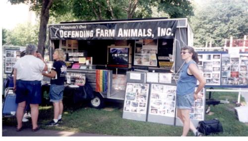
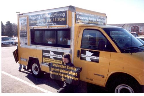
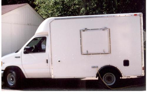
I built three mobile exhibits that were used to educate the public in animal welfare issues at hundreds of events primarily during the warm summer months.
Building these exhibits is the pinacle of my creative work. the core of who I am. They are the culmination of creativity, innovation, learning, discovery, and handyman skills brought together as a contemporary way of overturning some tables in the temple for social change. I loved researching existing technologies and integrating them in new ways to produce a unique solution that was orders of magnitude less expensive than professionally constructed exhibits.
The first exhibit was built from a used pop-up camper trailer. My brother gutted it and retrofitted the electrical, mechanical and air conditioning systems. I created several exhibits on topics such as animal testing, factory farming, pet overpopulation and animals used in entertainment. The trailer was heavily used for over ten years at over a hundred events.
The second exhibit was built from a GMC panel truck that we acquired from Penske Truck Rental. We had a horizontal doorway cut into one side of the truck to accommodate three large screen video displays. I designed a self-contained electrical system consisting of eight locomotive batteries, a power inverter, battery charger, and solar cells. The rooftop solar cells charged the batteries while parked in storage between events and shore power was available for quick charging. These batteries supplied 120 volts at 20 amps for over 12 hours which meant we could operate the exhibit without external power or a generator.
The third exhibit was much more elaborate and went to a national non-profit organization. We bought a brand-new GMC panel truck with a custom hinged opening on each side to accommodate a large television. Plasma TVs were available, but they did not perform very well in daylight, so we decided to go with massive CRT (picture tube) TVs. We ordered two Sony FD Trinitron Wega 36-inch TV’s. The screen was completely flat – something never achieved before. They were incredibly bright with little glare when used outdoors and were high definition capable. The downside is that each unit weighed in at 236 pounds and costs $2900. With the necessary steel structure to hold them safely in place and supporting electronics we ended up with close to a half ton of payload. We put in the same locomotive battery powered electrical system as in the previous truck.
It was a beautiful and road worthy exhibit that we passionately built in the heat of August. The last we heard it was being used as a cargo truck.
Isolated Technical Power
This is a special circuit dedicated to only sound equipment that originates from the power company feeder and runs throughout the building without ever touching anything that is grounded. The wire is carefully twisted to cancel radio frequency (broadcast radio and TV stations) interference and routed to minimize interactions with other systems in the building. A massive copper ground wire runs in parallel to provide a safety ground that originates deep in the church basement and is bonded to the two 10 foot copper rods drilled through the concrete floor and driven into the earth beneath the church basement. The other end of the ground wire terminates at each ISO power outlet by using a special duplex that maintains the isolation. These outlets are easily recognized by their bright orange color…and look just like the ones you would see in hospitals.
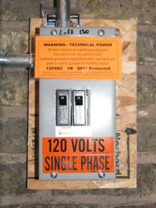
It took a couple of months to run cable from the boiler room up through two floors of offices, through a reinforced concrete firewall, inside a vertical fresh air shaft, parallel to a 4 story relief air shaft, across the attic, down through the ceiling into the balcony. The cable also ran from the attic to tunnels under the basement up to the choir loft and then up to the pipe organ chamber, terminating in a crawl space under the chancel. A relay box switches the high ampacity power for amplifiers and back-line equipment for the band. A toroidal power filter in the balcony provides refined power for sensitive digital equipment. Power to everything sound related throughout the entire building is engaged by one three-stage time-sequenced power switch and voltage monitor.
The church has unusual power – 3 Phase Delta with a High Leg. Under certain circumstances power can actually back feed down through the earth and up into our neighbors circuits causing technical equipment to malfunction. We maintain test equipment in the electrical room to rapidly troubleshoot such problems should they occur. This demarcation point is our first line defense in troubleshooting technology equipment that is experiencing power problems.
Boiler Monitor
Old steam boilers can be temperamental and require almost daily care. As a church we needed a way to determine why the boiler was not working without calling in a professional or expecting a volunteer to always be on call. I built a small diagnostic panel with a series of lights. When there is a call for heat from the thermostat the lights illuminate in sequence until the boiler turns on. If there was no heat, then all the pastor needed to do is look to see which lamp did not turn on and then reset the corresponding sensor. This would almost always resolve the issue and then let a volunteer look further into the issue at their convenience.
We went from 3-4 heat outs per month to a couple of resets per month. Once we were able to properly deal with the root cause we dropped to 1-2 resets for the entire heating season with no heat outs. The system became vastly more reliable for a total cost of $175. If we had replaced all the suspect components to improve reliability the cost would have been around $15,000.
To read more about this click here.